Home/News/CNC Machining Design Guideline: Maximizing Your Results
CNC Machining Design Guideline: Maximizing Your Results
March 29, 2024
CNC machining is a versatile manufacturing process that can produce a wide range of parts with high precision and repeatability. It is an essential manufacturing process for producing high-precision, complex parts for various industries, including aerospace, automotive, healthcare, and electronics.
But here’s the twist: achieving perfection in CNC machining isn’t just about the machinery. It’s an art form, requiring a keen eye for design and a deep understanding of the process. In this guide, we unravel the secrets of CNC machining design. From general best practices to bespoke tips for different CNC operations, we’re diving into how to sculpt your designs for peak CNC performance. Welcome to the intersection of innovation and precision, where every guideline we share is a step toward manufacturing excellence.
What Is CNC Machining?
In CNC machining, a part’s development progresses from the initial concept to the physical form through a precise and technologically advanced process. Initially, a CNC designer creates the design using advanced CAD software. This design is subsequently converted into G-code, the directive code for CNC machines. Following this code, the CNC machine utilizes specialized cutting tools to methodically sculpt the part from a solid block.
CNC machines like vertical & horizontal milling and lathes can operate on various axes. To create relatively simple parts, traditional 3-axis machines can manipulate parts along three linear axes (X, Y, and Z). The 5-axis machining can work along the three linear axes and around two rotational axes to create more complex components.
The subjective manufacturing process allows the production of high-precision and complex parts in various materials like metals, plastics, and composites. Furthermore, it is fast, automated, precise, and scalable which makes it applicable in prototyping, one-off production, and large-scale production.
CNC Design Guidelines: Cost Reduction Tips
Understanding what CNC machining is sets the foundation for appreciating the importance of adhering to design practices. These practices are essential for reducing costs and maintaining a high standard of quality and precision.
Common Design Guides for CNC Machining
Avoid Non-Planar and Draft Angle Surfaces
Non-planar and draft angle surfaces are complex and challenging to machine, which can result in slower cutting speeds, longer machining times, and increased tool wear. Additionally, these surfaces can make it more difficult to achieve consistent part quality and tight tolerance. To avoid non-planar and draft angle surfaces in your design:
Use simple and flat geometry whenever possible.
Use fillets and radii to soften sharp corners and reduce the number of complex surfaces.
Incorporate draft angles into your design to allow easy material removal and reduce tool wear during machining.
Increase the Size of Internal Fillets
Internal fillets are rounded corners or transitions within a part that can reduce stress concentrations and improve the part’s strength. Increasing the size of these fillets will enhance the machining operation’s quality and efficiency by:
Reducing cutting forces and tool wear during machining.
Improving chip removal and material flow during cutting.
Reducing the likelihood of tool breakage and premature tool wear.
Improving surface finish and part quality.
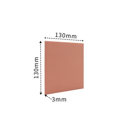
Add Undercuts to Sharp Corners
Undercuts are recesses or notches in the corners of a part that allow for better tool access and improved material removal during machining. An optimized undercut design for CNC machining will:
Reduce cutting forces and tool wear.
Improve chip removal and material flow during cutting.
Reduce the likelihood of tool breakage and premature tool wear.
Improve the part’s surface finish and part quality.
However, creating undercuts can be a complex and challenging task because they can be difficult to reach using standard cutting tools. Furthermore, specialized tools or multi-axis machining may be required to machine undercuts. Minimizing the size and complexity of undercuts can help achieve better results. The following should be taken into consideration when designing undercuts:
Recommended
Undercut dimension
3 mm to 40 mm
Undercut clearance
4x depth
Use Standard Tolerances
Standard tolerances ensure that finished CNC parts meet the desired specifications and functional requirements. Unnecessary tight tolerances can increase the cost and time of machining.
By specifying standard CNC machining tolerances, manufacturers can reduce the need for secondary operations and improve the overall efficiency of the machining process.
Recommended
Feasible
Tolerances
±0.1 mm
±0.02 mm
Text and Lettering
When creating text or lettering, the tool must be able to maintain a constant width, height, and spacing throughout the machining process. Any variation in these factors can result in a final product that doesn’t meet design specifications.
You need to consider the font and size of the text or lettering. Texts that are too small may be difficult to read or they may not meet the desired specifications while texts that are too large may cause tool deflection or affect the accuracy and precision of the machining process. To address these challenges, some good design practices recommended by engineers and designers:
Use standard fonts well-suited for the machining process
Avoid overly complex or fine lettering
Specify a larger font size
Opt for a font with a more consistent width, height, and spacing
Carefully consider the orientation of the text relative to the workpiece
Adjust the tool accordingly to maintain a consistent height, spacing, and cutting speed.
Part Size
CNC machines have varying capabilities based on their size and capacity. Some machines may be too small to accommodate large parts, while others may not be able to handle parts that are too small. As a result, the parts to be designed should carefully consider the part size and choose the appropriate machine accordingly.
In addition to the size of the machine, the part size can also impact the speed of the machining process. Larger parts have a longer machining time and higher production costs because engineers need to remove more material during machining compared to smaller parts.
Maximum Dimension
Minimum Dimension
CNC Milling
4000×1500×600 mm 157.5×59.1×23.6 in.
4×4 mm 0.1×0.1 in.
CNC Turing
200×500 mm 7.9×19.7 in.
2×2 mm 0.079×0.079 in.
Choose Softer Material
Softer materials are easier to machine, resulting in faster cutting speeds, reduced tool wear, and lower machining times and costs. Additionally, they are less prone to cracking or deformation during the machining process, which improves part quality and reduces post-machining processing time. Nevertheless, only choose a soft material if the intended use and final application of the product allow it.
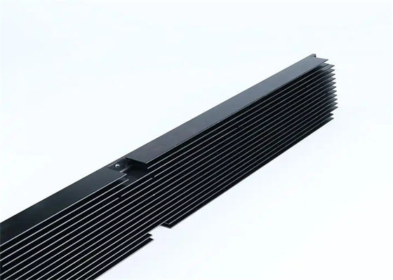
Minimize Tool Changes and Workholding Setups
A higher need for tool changes and work holding setups during a machining cycle will lead to a time-consuming and expensive process. You can consider the following tips to minimize tool changes and setups:
Parts with similar features and geometries can be CNC machined using a single cutting tool.
Reduce the required setups by designing parts with consistent orientations or using modular fixtures that can accommodate multiple parts.
Use multi-functional cutting tools that can perform multiple operations with a single tool change.
For CNC Milling Parts
Keep Available CNC Cutting Tools in Mind
Optimizing CNC parts for cost and lead time reduction involves aligning designs with the capabilities of standard CNC milling tools. By choosing designs that conform to the sizes and capabilities of these standard tools, the need for custom or specialty tools can be significantly minimized.
A practical example is the design of internal fillets. It’s advisable to avoid specifications that require a radius smaller than what standard CNC cutting tools can accommodate. Creating such features necessitates switching to smaller, possibly custom tools, which could lead to increased time and costs that may not justify the benefits. Therefore, staying within the limits of standard tool capabilities is a key consideration for efficient CNC part production.
Avoid Sharp Internal Corners
CNC milling has inherent limitations, one of which is the inability to create sharp internal corners. This limitation arises from the round shape of CNC milling tools. To navigate this, engineers often use radiused corners in their designs. The radius of these corners needs to be at least half the diameter of the milling cutter. For example, with a 1/4” cutter, the minimum radius for the fillets should be no less than 1/8”.
To address the challenge of sharp corner requirements in parts, specific design approaches are employed. These include:
Drilling holes to “break” the corners.
Allowing sharp edges to fit within the cavity.
Using fillets when sloped or drafted surfaces meet vertical walls or sharp edges.
Using square or ball end mills will always result in material between the wall and surface unless the surface is flat and normal to the tool.
Avoid Deep, Narrow Slots or Pockets
A good design practice is that the final depth of cut should not exceed certain ratios based on the material to be machined. For instance, with plastics, the ratio should not be greater than 15 times the diameter of the end mill, aluminum should be no more than 10 times, and steel’s limit is 5 times. This is because longer tools are more susceptible to deflection and vibration, leading to surface imperfections.
Furthermore, the internal fillet radius also depends on the diameter of the cutting tool. If a 0.55” wide slot for a steel part is to be CNC machined using a 0.5” end-mill, then the depth should not exceed 2.75”. Furthermore, high length-to-diameter ratio end mills can be harder to obtain. Hence, it is advisable to either decrease the depth of the slot or feature or increase the diameter of the cutting tool.
Recommended
Feasible
Cavity Depth
4 times cavity width
10 times the tool diameter or 25 cm
Design the Largest Allowable Internal Radii
The cutting tool size used in CNC mills should be considered during the design phase. A larger cutter removes more material in one pass, reducing machining time and costs.
To take full advantage of the capabilities of larger cutters, design your internal corners and fillets with the largest possible radius, preferably greater than 0.8mm.
An added tip is to make the fillets slightly bigger than the end-mill’s radius, such as a radius of 3.3mm instead of 3.175mm. This creates a smoother cutting path and produces a finer finish on your machined part.
Recommended
Internal Corner Radius
⅓ times cavity depth (or larger)
Choose Suitable Thickness
It is important to note that thin walls in parts can create significant challenges in the machining process, especially in terms of maintaining stiffness and accuracy of dimensions. To avoid these difficulties, you can design walls with a minimum thickness of 0.25mm for metal components and 0.50mm for plastic parts as they can withstand the rigors of the manufacturing process.
Recommended
Feasible
Wall Thickness
1.5 mm (plastics), 0.8 mm (metals)
1.0 mm (plastics), 0.5 mm (metals)
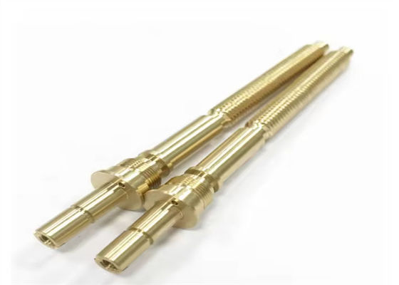
For CNC Turning Parts
Avoid Sharp Internal Corners
Sharp internal and external corners in a part design can be a challenge during machining. To overcome this issue, it’s recommended to:
Have radiused internal corners, providing a gradual transition for the tool to move smoothly.
Incorporate a slight angle in the steep sidewalls to eliminate sharp internal corners.
Simplify the machining process by reducing the number of operations required with a single tool.
Avoid Long, Thin Turned Parts
Instability is a common concern when it comes to long, thin-turned parts. The spinning part can easily chatter against the tool, creating an imperfect finish. To combat this, make use of the following CNC design tips.
Incorporate a center drill at the end and use a center to keep the part spinning in a straight manner.
Keep the length-to-diameter ratio at or below 8:1 to minimize the risk of instability during machining.
Avoid Thin Walls
During a CNC turning operation, be mindful of the amount of material being machined away. Over-machining can result in undue stress on the part, while thin walls can result in decreased stiffness and difficulty in maintaining tight tolerances.
As a guideline, the wall thickness of turned parts should be at a minimum of 0.02 inches to ensure stability and accuracy during the manufacturing process.
Recommended
Feasible
Wall Thickness
1.5 mm (plastics), 0.8 mm (metals)
1.0 mm (plastics), 0.5 mm (metals)
For Drilling Parts
Optimal Hole Depth
The ideal depth of a drilled hole should balance the stability of the tool and the strength of the material being machined. Drilling too shallow can result in a weak joint and reduce the holding power of screws while drilling too deep can cause the drill bit to break or bend, leading to poor accuracy and surface finish.
To determine the optimal hole depth, you must consider the drill bit’s size, the material’s hardness and thickness, the strength required for the intended application, and the overall stability of the machine setup. Drilling the hole just deep enough to accommodate the screw or fastener is recommended, leaving some material for support. If a countersink is required, then the hole should be drilled deeper to allow for the countersink.
Recommended
Feasible
Hole Depth
4 times the nominal diameter
40 times the nominal diameter
Distinguish Through Holes and Blind Holes
Understanding the difference between through holes and blind holes is important, as they both require different drilling techniques and tools.
A through hole is a hole that extends entirely through the workpiece from one end to the other. It is generally easier to produce, as the drill must enter and exit the part at opposite sides. Through holes are applicable in the fastening, mounting, and routing of electrical and mechanical components.
Blind holes, on the other hand, do not go all the way through the workpiece and stop at a specific depth. They are applicable in creating cavities, recesses, or pockets within the workpiece and are generally more challenging to produce than through holes. Blind holes require special CNC drill bits and cutting speeds to ensure that the cutting edge does not break through the bottom of the part.
Through Holes
Blind Holes
Tip 1: Determine the correct drill size
Tip 1: It should be 25% longer than the needed depth
Tip 2: Maintain rigidity
Tip 2: Use a center drill
Tip 3: Use proper cutting fluids
Tip 3: Ensure sufficient hole depth above the drill tip
Tip 4: Monitor drill speed
Tip 4: Reduce speed and feed rates
Tip 5: Drill in stages
Tip 5: Avoid reaming
Avoid Partial Holes
A partial hole occurs when the drill does not fully penetrate the material and can be caused by various factors such as the drill bit breaking, incorrect drill bit selection, or incorrect parameters such as speed, feed, and depth of cut. Therefore, you should select the right drill bit, maintain the right parameters, and use coolant to dissipate heat.
Avoid Drilling Through Cavities
While drilling, keep in mind that intersecting holes with existing cavities in parts can compromise its structural integrity. You can avoid this by positioning the drill points away from existing cavities. However, if the drilled hole must cross the cavity, a working practice is to make sure that its center axis does not intersect with it to maintain the part’s stability.
Design Standard Drill Size
Optimize your design for standard drill sizes to save time and money, and make it easier for machine shops to produce your part without needing costly custom tooling.
Consider using a standard drill size like 0.12” instead of a more precise but less common size like 0.123”. Also, try to limit the number of different drill sizes used in your CNC design, as multiple sizes increase the time and effort required for tool changes during the machining process.
Recommended
Feasible
Drill Size
Standard drill bit (0,12”)
Any diameter larger than 1 mm
Specify Threaded Holes
A threaded hole allows for the attachment of bolts, screws, and other threaded fasteners. Make sure to specify the correct depth of the thread so that the threaded fastener has enough engagement to hold the part together. The deeper the thread, the stronger the fastener grip.
The type of material can affect the type of thread. On the one hand, soft materials may require a shallower thread. On the other hand, harder materials may need a deeper thread.
When specifying threaded holes in a drawing, use clear and accurate thread callouts to ensure the correct thread standard, pitch, and depth. Ensure enough clearance for the installation and removal of the threaded fastener without binding or stripping the thread.
Recommended
Feasible
Thread Length
3 times the nominal diameter
1.5 times the nominal diameter
Avoid Deep Taps
Another crucial tip to achieve accurate and precise results is to avoid deep taps. The longer the tap, the greater the risk of it vibrating and wandering while in operation, leading to imperfections in the final product. A tap that exceeds 3 times its diameter is deep and can pose a significant challenge.
However, in many cases, even a tap that goes 1.5 times the diameter will provide ample thread engagement, thereby eliminating the need for a deep tap. Using deep taps increases the risk of tool breakage, flawed threads, and diminished precision, making it an undesirable aspect of CNC machining design.

 Your message must be between 20-3,000 characters!